
It’s been a while since I contributed to these pages. I’ve been involved with a variety of other projects including writing another book in the Colonel Unthank’s Norwich series: Post Scripts, which should come out this autumn. In this I write about The United Friars – probably the most fascinating subject I’d come across, based on a tantalising notebook in the Norfolk Record Office.
Formed in Norwich in 1785 the Friars were a group of men including well-known painters, architects, bankers, authors, a newspaper proprietor, a surgeon, a pomologist etc. These were the city’s enquiring minds; the intelligentsia who sought enlightenment in a way that would not have been tolerated under the religious oppression of the previous century. Indeed, the Friars seemed to be celebrating their freedom of expression by wearing monk’s habits and a pink cloth ‘tonsure’. The Brothers, some of whom were of national standing, were far from a frivolous drinking group; their discussions were serious and they made large sums of money to feed the poor.
Religion and politics were excluded from discussion but, otherwise, the range of topics was as diverse as the membership. As a one-time scientist I was intrigued by the inclusion of scientific subjects within their scope of enquiry. They paid a local schoolmaster to look after their instruments that included a microscope and an electrical discharge measuring device. While I’m familiar with looking down a microscope I know nothing about electrical devices and would really appreciate any information you can provide. Please reply if you know how this operates.
The answer
John Fielding, with some help from ChatGPT, replied with the best description of the instrument referred to in this drawing:
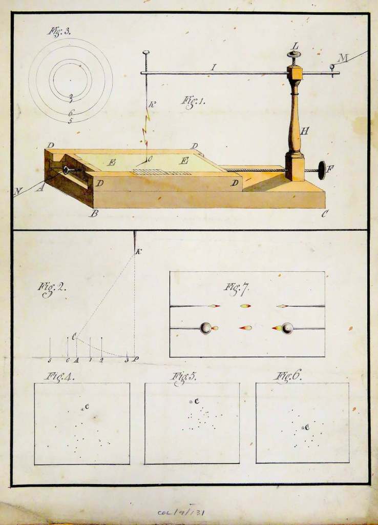
“This is not simply a conventional electrometer with a pointer. It appears to be an experimental balance for measuring the mechanical force produced by static electricity.
The important part is Fig. 1. The tall pillar H supports the long horizontal beam I, which can pivot very freely at L. That makes it essentially a delicate balance. The small movable weight at M can be slid along the right-hand end of the beam. At the opposite end, the fine vertical thread K connects the balance to the experimental piece at O.
So the experiment would work roughly like this:
- The beam is first balanced. The weight M is adjusted until the long arm I sits at its reference position.
- Static electricity is applied to the conductors in the apparatus. In the 1780s this would have been supplied by a frictional electrical machine, very probably with a Leyden jar or battery if a substantial discharge was required.
- At O, the electrical charge produces an attractive or repulsive mechanical force between the conducting parts. That force tries to move O.
- Because O is attached by the fine thread K to the balance beam, the electrical force causes I to tilt.
- The experimenter then moves the little counterweight M until the beam is brought back into equilibrium. Because the weight and its distance from the pivot are known, the experimenter can calculate the force that the electricity is exerting.
In modern terms, it is rather like putting electricity on a very sensitive set of scales. Instead of saying, “that’s quite a big spark”, the experimenter can say, in effect, “that electrical charge exerted this much force.”
That interpretation also makes sense of the other drawings. Fig. 2 appears to plot the force against distance, while Fig. 3 shows a series of distances or radii. Figs. 4–6 appear to record the physical distribution or effects obtained in different trials, and Fig. 7 shows different arrangements of conducting points or balls and the electrical discharge between them.
When I wrote the post I inserted the drawing adjacent to the entry for Blyth Hancock, the schoolmaster who was paid by the other Brothers to look after the Society’s scientific instruments, but the drawing is better attributed to James Bennett, one-time Sheriff and last surviving Friar who died in 1845. It was Bennett who was acknowledged as the person to have made the first electrical machine in Norwich. Though the drawing is undated, Bennett is not recognised as the inventor of the measuring electrometer. However, as a master horologist, in partnership with watchmaker Peter Amyot, the precision gears applied to an existing concept would have made a much more accurate mapping tool.


Dear Colonel Unthank
Thank you so much for reassuring us that you were still actively involved in recording and making accessible the history of Norwich.
I was starting to wonder if you had left us.
I have no idea how the electrical discharge measuring device works and shall be pleased to find out. Someone among us will know.
I am looking forward to getting your Post Scripts book.
John C. Ward ________________________________
LikeLike
Appreciate the kind words John. I am still with us, wondering how to send out something briefer than all-consuming blog posts
LikeLike
Good to hear from you again, Colonel! Look forward to the book DS
LikeLike
Thank you Deidre. I’ve reserve a copy
LikeLike
Brilliant 🙂 D x
LikeLike
So so glad you’re in action again! This sounds fascinating. Heather x
LikeLike
Thank you Heather. Building up the next book.
LikeLike
Great to see you back, Reggie. Looking forward to buying your next book!
ChatGPT says this about the instrument in your drawing:
This is not simply a conventional electrometer with a pointer. It appears to be an experimental balance for measuring the mechanical force produced by static electricity.
The important part is Fig. 1. The tall pillar H supports the long horizontal beam I, which can pivot very freely at L. That makes it essentially a delicate balance. The small movable weight at M can be slid along the right-hand end of the beam. At the opposite end, the fine vertical thread K connects the balance to the experimental piece at O.
So the experiment would work roughly like this:
In modern terms, it is rather like putting electricity on a very sensitive set of scales. Instead of saying, “that’s quite a big spark”, the experimenter can say, in effect, “that electrical charge exerted this much force.”
That interpretation also makes sense of the other drawings. Fig. 2 appears to plot the force against distance, while Fig. 3 shows a series of distances or radii. Figs. 4–6 appear to record the physical distribution or effects obtained in different trials, and Fig. 7 shows different arrangements of conducting points or balls and the electrical discharge between them.
LikeLike
John, That’s an amazing description of the electrical device. I had managed to find that this appears to be a version of Timothy Lane’s Discharging Electrometer but your ChatGPT description adds much more. Thank you. Reggie
LikeLike